How to create a solid object?
How to create a solid object?
Hi community, i have been studying the tutorials and it helped me to start my research on the irrlicht engine. So far i was able to create my first examples with C# and Irrlicht, so in order to make more progress in my project i need some additional guidance:
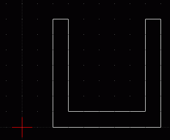
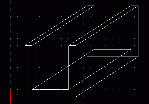
I have a bidimensional cross-section (basically a polygon of "n" vertex defined in my application) and i want to create a solid-body based on that polygon. The idea is to extrude the poligon in Z axis and create the solid. How can i create this mesh / solid?. Obviously, i don't want to use any other modeling software because i will need to change the cross-section in my application and update the solid-body by re-generating it.
Any ideas on how to create my solid object in realtime?
Thanks in advance.
Do you mean a solid object in the sense that it is solid all the way through, unlike a cube mesh which would just be a cube mesh frame which if you tried to go inside would be empty?
Or do you just want to create a 3D mesh from a 2D shape?
I suppose to make a 3D mesh you'd sort of copy the polygon and move it to where you want the end of the extrusion to be and then connect up all the edge vertices to the original polygon.
Or do you just want to create a 3D mesh from a 2D shape?
I suppose to make a 3D mesh you'd sort of copy the polygon and move it to where you want the end of the extrusion to be and then connect up all the edge vertices to the original polygon.
-
hybrid
- Admin
- Posts: 14143
- Joined: Wed Apr 19, 2006 9:20 pm
- Location: Oldenburg(Oldb), Germany
- Contact:
Yes, JP's description covers the whole extrusion process. You can make use of some of Irrlicht's methods to simplify this work:
MeshManipulator->transform(buffer, matrix) transforms a meshbuffer according to the matrix given. This could be a simply translate into one direction. Create a copy of the buffer first... Since you have to change the winding order of the mesh, you mihgt have to scale by (-1,-1,-1) as well.
meshbuffer->append(meshbuffer) will add the transformed meshbuffer to the original one. Now you have 2n vertices in there.
The sides are created by adding indices only. The vertices all exist already. So add vertices i,i+1,i+n,i+1,i+n+1,i+n for i=0..n-2 and the final faces with n-1,0,n,0,n+1,n. Please take care of off-by-one errors in those indices, I just wrote them down without checking them.
I think this would make an interesting meshmanipulator method Note, though, that this does work for convex meshes with consecutive vertices only. Everything else would require much more checks on the actual vertex positions and face relations.
MeshManipulator->transform(buffer, matrix) transforms a meshbuffer according to the matrix given. This could be a simply translate into one direction. Create a copy of the buffer first... Since you have to change the winding order of the mesh, you mihgt have to scale by (-1,-1,-1) as well.
meshbuffer->append(meshbuffer) will add the transformed meshbuffer to the original one. Now you have 2n vertices in there.
The sides are created by adding indices only. The vertices all exist already. So add vertices i,i+1,i+n,i+1,i+n+1,i+n for i=0..n-2 and the final faces with n-1,0,n,0,n+1,n. Please take care of off-by-one errors in those indices, I just wrote them down without checking them.
I think this would make an interesting meshmanipulator method
Thanks for the replys.
I checked the documentation but is not so explained, for example Irrlicht Manual (http://www.irrlicht3d.org/wiki/index.ph ... ichtManual) is incomplete and all the definitions (meshes, vertex, indexes, etc.) i need to read are not in that document. Where else can i found complete documentation? just reading the tutorials?.
Let me explain what i am trying to do:
My application has the 2d polygon definition (based on the vertexes) and the user can modify the poligon. Now, i want to draw this 2d polygon in Irrlicht, how can i acomplish that?

Additionally, i want to create a solid based on that polygon. The first idea that come to my mind is to extrude the polygon as you can see in this image.

But how can i make this in Irrlicht?. Also, how do i convert all points and lines into a solid body (a solid all the way through) ?, how do i generate the SceneNode based on my solid-body?.
I need some guidance with little example or code fragment that show me the basics and i can continue...
Thanks for taking the time answering.
I checked the documentation but is not so explained, for example Irrlicht Manual (http://www.irrlicht3d.org/wiki/index.ph ... ichtManual) is incomplete and all the definitions (meshes, vertex, indexes, etc.) i need to read are not in that document. Where else can i found complete documentation? just reading the tutorials?.
Let me explain what i am trying to do:
My application has the 2d polygon definition (based on the vertexes) and the user can modify the poligon. Now, i want to draw this 2d polygon in Irrlicht, how can i acomplish that?

Additionally, i want to create a solid based on that polygon. The first idea that come to my mind is to extrude the polygon as you can see in this image.

But how can i make this in Irrlicht?. Also, how do i convert all points and lines into a solid body (a solid all the way through) ?, how do i generate the SceneNode based on my solid-body?.
I need some guidance with little example or code fragment that show me the basics and i can continue...
Thanks for taking the time answering.
Try this article, it might help you understand the concept.
http://www.geocities.com/foetsch/extrude/extrude.htm
http://www.geocities.com/foetsch/extrude/extrude.htm

Hi, thanks for all the replys...and i am back again 
This is the code i have done:
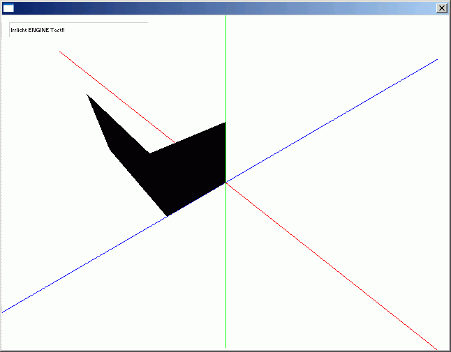
And this is what i got:

My solid have 4 faces (triangles) defined by ArrayVertices[] and the indices of the triangles are in mb.Indices.
I also draw the axes to give me the orientation of the axes.
These are my questions:
* The orientation of the axis is not ok. It's not coherent what i have drawn with the direction of the axis. This is really important, and don't know why is happening!!!
* Why is everything black?
* How can i see the Wireframe of the solid?
* I used Indices for each triangle (face) of the solid. Can i generate the Mesh using Quads instead of Triangles?. How? (All my quads are in the same plane).
* What does the BoundingBox class do with the Mesh, why should i use the BoundingBox class and what for?
Thanks everybody for spend time to read, regards.
This is the code i have done:
Code: Select all
    class Program
    {
        static VideoDriver Driver;
        static SceneManager Scene;

        static void Main(string[] args)
        {
            IrrlichtDevice Device = new IrrlichtDevice(DriverType.OpenGL, new Dimension2D(640, 480), 16, false, true, true, true);

            Driver = Device.VideoDriver;
            Scene = Device.SceneManager;
            GUIEnvironment guienv = Device.GUIEnvironment;

            // Some text
            guienv.AddStaticText("Irrlicht ENGINE Test!!",
                new Rect(new Position2D(10, 10), new Dimension2D(200, 22)), true, false, guienv.RootElement, -1, false);

            //LightSceneNode light = Scene.AddLightSceneNode(null, new Vector3D(0, 200, 0), Colorf.White, 400, -1);

            // Mesh Node
            Mesh Solid = new Mesh();
            MeshBuffer mb = new MeshBuffer(VertexType.Standard);

            Vertex3D[] ArrayVertices = new Vertex3D[6];

            ArrayVertices[0] = new Vertex3D();
            ArrayVertices[1] = new Vertex3D();
            ArrayVertices[2] = new Vertex3D();
            ArrayVertices[3] = new Vertex3D();
            ArrayVertices[4] = new Vertex3D();
            ArrayVertices[5] = new Vertex3D();

            ArrayVertices[0].Position = new Vector3D(0, 0, 0);
            ArrayVertices[1].Position = new Vector3D(50, 0, 0);
            ArrayVertices[2].Position = new Vector3D(50, 50, 0);
            ArrayVertices[3].Position = new Vector3D(0, 50, 0);
            ArrayVertices[4].Position = new Vector3D(50, 0, -100);
            ArrayVertices[5].Position = new Vector3D(50, 50, -100);

            for (uint i = 0; i < ArrayVertices.Length; i++)
            {
                mb.SetVertex(i, ArrayVertices[i]);
            }

            mb.Indices = new ushort[12] { 0, 1, 2,
                                         0, 2, 3,
                                         1, 4, 5,
                                         1, 5, 2};

            Solid.AddMeshBuffer(mb);

            SceneNode SolidNode = Scene.AddMeshSceneNode(Solid, null, -1);
            SolidNode.SetMaterialFlag(MaterialFlag.Lighting, false);

            // Camera
            CameraSceneNode cam = Scene.AddCameraSceneNodeMaya(null, 200f, 200f, 100f, -1);
            cam.Position = new Vector3D(100, 100, 100);

            // Loop
            while (Device.Run())
            {
                Driver.BeginScene(true, true, Color.White);
                Scene.DrawAll();
                guienv.DrawAll();

                // Draw XYZ Axes
                Driver.Draw3DLine(new Line3D(-500f, 0f, 0f, 500f, 0f, 0f), Color.Blue); //X
                Driver.Draw3DLine(new Line3D(0f, -500f, 0f, 0f, 500f, 0f), Color.Green); //Y
                Driver.Draw3DLine(new Line3D(0f, 0f, -500f, 0f, 0f, 500f), Color.Red); //Z

                Driver.EndScene();
            }
            Device.Dispose();
        }
    }

My solid have 4 faces (triangles) defined by ArrayVertices[] and the indices of the triangles are in mb.Indices.
I also draw the axes to give me the orientation of the axes.
These are my questions:
* The orientation of the axis is not ok. It's not coherent what i have drawn with the direction of the axis. This is really important, and don't know why is happening!!!
* Why is everything black?
* How can i see the Wireframe of the solid?
* I used Indices for each triangle (face) of the solid. Can i generate the Mesh using Quads instead of Triangles?. How? (All my quads are in the same plane).
* What does the BoundingBox class do with the Mesh, why should i use the BoundingBox class and what for?
Thanks everybody for spend time to read, regards.
-
hybrid
- Admin
- Posts: 14143
- Joined: Wed Apr 19, 2006 9:20 pm
- Location: Oldenburg(Oldb), Germany
- Contact:
The orientation might be wrong due to wrong vertex winding. Irrlicht uses clockwise orientation, but you use counter-clockwise. Maybe try with backface culling disabled first.
The black color is due to uninitialized color values in the s3dvertex objects. However, using white wouldn't show anything
Wireframe can be turned on in the material.
Quads are currently only supported for OpenGL. Also, it's not much more work with triangles, and several algorithms of Irrlicht expect tri lists.
The bounding box is necessary for proper frustum culling, collision detection, and other things. It's a cuboid which encompasses all vertices of the mesh. Just reset the box to the first vertex added, and add all other with the bbox method addInternalPoint.
When you say the orientation is wrong what do you mean?. I have to invert the indices to clockwise orientation for all the triangles?.
Why do i have to use that orientation? i do not understand how does it affects the rendering and how it works.
Where can i see any documentation that can help me clarify this?
Why do i have to use that orientation? i do not understand how does it affects the rendering and how it works.
Where can i see any documentation that can help me clarify this?
I'll write some pseudo code. It probably wont help much, but might give you an idea
After thinking about it, the only real task would be to find the lines in the mesh that are too copy
Code: Select all
for each vertex {
   for each vertex attached to this one {
      if(line is against nothing) {
          create poly in square* distance away
      }
   }
}
Last edited by torleif on Thu Aug 28, 2008 7:36 am, edited 1 time in total.
-
hybrid
- Admin
- Posts: 14143
- Joined: Wed Apr 19, 2006 9:20 pm
- Location: Oldenburg(Oldb), Germany
- Contact:
The winding order defines the front side of a triangle. It's necessary because with just a list of points you cannot tell which side of the tri should be front and which one back (or inside and outside of a mesh...). This is used in all 3d APIs. If you don't want to see a difference between front and back side you just have to disable the backface culling (although lighting will still be strange on back faces).
Anyway, yes, just change the order of the indices to make the same triangle look into the other direction.
Anyway, yes, just change the order of the indices to make the same triangle look into the other direction.
