draw a rays or 3d line in an angle.

If you are a new Irrlicht Engine user, and have a newbie-question, this is the forum for you. You may also post general programming questions here.
Post Reply
phillip
Posts: 14
Joined: Thu Nov 05, 2009 9:04 pm

draw a rays or 3d line in an angle.

Post by phillip »

Hello Everyone I need some help with a task I would like to achieve. I checked the forum but I'm not sure what to search for when it comes to the name or the technical term for what I would like to achieve. I'm trying to draw/cast a 3d lines in an angle based on the rotation and position of my cube node. I was able to render a 3d line in front of my cube and it rotates perfectly based on my cubes rotation and movement. with the below code. I'm trying to achieve the red lines in the attached image. Not sure of the vector math I would need to do this. Can anyone help? Thank you.

Image

Code: Select all

SMaterial m;
m.Lighting = true;
m.Thickness = 1.0;
driver->setMaterial(m);
driver->setTransform(video::ETS_WORLD, core::matrix4());

vector3df facing;
facing.Z += cos(node->getRotation().Y * PI/180.0f)*200;
facing.X += sin(node->getRotation().Y * PI/180.0f)*200;

driver->draw3DLine(cube->getPosition(),cube->getPosition()+facing,SColor(255,255,255,255));
Last edited by phillip on Mon Jul 11, 2022 12:00 pm, edited 3 times in total.
CuteAlien
Admin
Posts: 9670
Joined: Mon Mar 06, 2006 2:25 pm
Location: Tübingen, Germany
Contact:

Re: draw a rays or 3d line in an angle.

Post by CuteAlien »

cube->getRelativeTransformation gives you the matrix you need.
Or cube->getAbsoluteTransformation (if it has parent nodes) - in which case you should call updateAbsoluteTransformation if you need it before the cube rendering (updateAbsoluteTransformation is called shortly before it's render call otherwise, if it's not called before you get the matrix it will be one frame behind).

Once you have your matrix you can transform any vector you want to be transformed the same as the node by calling the transformVect function on that matrix. But be aware that it also does scaling - which is not always what you want when drawing such lines. If you want the matrix, but without scaling, check the code in ISceneNode::getRelativeTransformation and just leave out the scaling part. Well - check that code anyway to see how that matrix is created (pretty simple).

Note that if you have normals instead of vectors you have to use the inverse/transposed matrix instead (vector would be transformed correct, but they won't be normals to the rotated polygons anymore).
IRC: #irrlicht on irc.libera.chat
Code snippet repository: https://github.com/mzeilfelder/irr-playground-micha
Free racer made with Irrlicht: http://www.irrgheist.com/hcraftsource.htm
phillip
Posts: 14
Joined: Thu Nov 05, 2009 9:04 pm

Re: draw a rays or 3d line in an angle.

Post by phillip »

@CuteAlien thank you for the replay. I manage to get it going. I'm not sure if this it the best way. but it works for now. Here is what I did to achieve what I needed.


Image

Code: Select all

SMaterial m;
m.Lighting = true;
m.Thickness = 1.0;
m.setFlag=true;

driver->setMaterial(m);
driver->setTransform(video::ETS_WORLD, core::matrix4());

vector3df prot=cube->getRotation();
vector3df ppos=cube->getPosition();

vector3df lineAngleA=getDirectionFromAngle(-45/2+prot.Y);
vector3df lineAngleB=getDirectionFromAngle(45/2+prot.Y);

driver->draw3DLine(ppos,ppos+lineAngleA*180,SColor(255,255,0,0));
driver->draw3DLine(ppos,ppos+lineAngleB*180,SColor(255,255,0,0));
driver->draw3DLine(ppos,ppos+forw,SColor(255,255,255,255));

vector3df getDirectionFromAngle(float angle){
vector3df res(sin(angle*DEGTORAD),0.0f,cos(angle*DEGTORAD));
return res;
}
Last edited by phillip on Mon Jul 11, 2022 11:56 am, edited 1 time in total.
CuteAlien
Admin
Posts: 9670
Joined: Mon Mar 06, 2006 2:25 pm
Location: Tübingen, Germany
Contact:

Re: draw a rays or 3d line in an angle.

Post by CuteAlien »

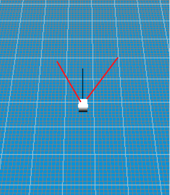
Yeah, that works as long as your cube won't look up (aka - as long as you stay in 2d and only rotate around Y).
With matrix you could replace the lineAngle calculations like that then should work also when the cube rotates up:

Code: Select all

vector3df lineAngleA=getDirectionFromAngle(-45/2);
vector3df lineAngleB=getDirectionFromAngle(45/2);
irr::core::matrix4 mat;
mat.setRotationDegrees( prot);
mat.transformVect(lineAngleA);
mat.transformVect(lineAngleB);
(tiny side note - using code marker you can format code like this in the forum)

So I took the +prort.Y out of the angle calculation and do that part with a matrix instead.
If you have pure rotation matrix (or a rotation + scaling matrix) then only the inner 3x3 matrix is really used.
So for this case you can also use mat.rotateVect which unlike transformVect only uses the 3x3 matrix (despite it names it will also scale if you have a scale matrix). transformVect is needed if you also want to add the position (translation).

And a quick note about SMaterial. I guess the setFlag = true was copy paste error. But careful with material.Lighting = true; Then your lines only show if there is also a light-source in your scene. If those lines are for debugging you generally want to turn lighting off - then they have the exact color you set.

Edit: Just for fun a quick explanation what that 3x3 matrix does (and I really hope I don't mess it up, for the full deal better watch those videos https://www.youtube.com/playlist?list=P ... itgF8hE_ab):
If you have x,y,z vector what it really means is - take x steps along x axis, then y along y axis and z steps along z-axis.
Matrixes are now the idea: What if you use axes which point in other directions?
Then you can still say - go x steps along first axis, y steps along second and z steps along third axis.
A bit like a treasure-map which has 3 directions drawn you have to follow.
And the first 3 rows in the 3x3 matrix are simply those 3 directions (ignore the 4th value in those rows, it's set to 0 for this case). So calculation is x*(axis1)+y*(axis2)+z*(axis3).
Original cartesian coordinate matrix is (1,0,0)(0,1,0)(0,0,1) (as you do 1 steps toward x-y-z in each direction there, also called the identity matrix). If you do the calculation there you'll find out you just get back x,y,z.

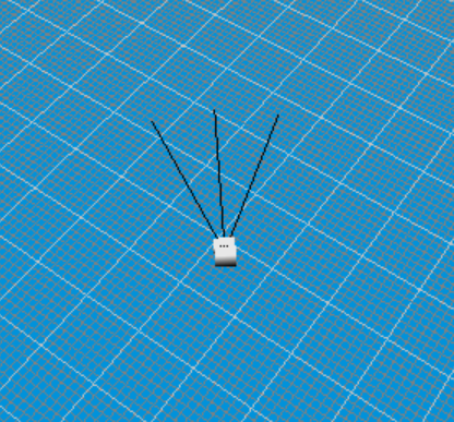
Now the trick is finding direction for the 3 axes so they point in the same direction as your cubeNode.
And that's where the same kind of sin/cos calculations you did above come into play.
matrix4::setRotationDegrees (or setRotationRadians which it calls) uses those to rotate the original 3 x,y,z axes into the same direction as your cubeNode.

And rotateVect then simply steps along those 3 directions given by the matrix (while transformVect adds the 4th row as well which moves your vector after rotating/scaling it).
And if think like that you also notice how rotation and scale are a bit mixed up in the 3x3 matrix (you take longer steps by using larger matrix values, but direction stays the same).
IRC: #irrlicht on irc.libera.chat
Code snippet repository: https://github.com/mzeilfelder/irr-playground-micha
Free racer made with Irrlicht: http://www.irrgheist.com/hcraftsource.htm
phillip
Posts: 14
Joined: Thu Nov 05, 2009 9:04 pm

Re: draw a rays or 3d line in an angle.

Post by phillip »

Awesome support!!!!! Thank you for sharing the knowledge. It's much appreciated.
Seven
Posts: 1030
Joined: Mon Nov 14, 2005 2:03 pm

Re: draw a rays or 3d line in an angle.

Post by Seven »

in case it is useful, here are a few functions I use...

Code: Select all

        // returns the direction that the node is 'looking'
	vector3df IGE_Object::getIn()
	{
		if (getPrimarySceneNode())
		{
			matrix4 mat = getPrimarySceneNode()->getRelativeTransformation();
			vector3df in(mat[8], mat[9], mat[10]);
			in.normalize();
			return in;
		}
		else return vector3df(0, 0, 0);
	}

        // returns the direction that points 'left' of where the node is 'looking'
	vector3df IGE_Object::getLeft()
	{
		if (getPrimarySceneNode())
		{
			matrix4 mat = getPrimarySceneNode()->getRelativeTransformation();
			vector3df left(mat[0], mat[1], mat[2]);
			left.normalize();
			return left;
		}
		else return vector3df(0, 0, 0);
	}

        // returns the direction that points 'up' of where the node is 'looking'
	vector3df IGE_Object::getUp()
	{
		if (getPrimarySceneNode())
		{
			matrix4 mat = getPrimarySceneNode()->getRelativeTransformation();
			vector3df up(mat[4], mat[5], mat[6]);
			up.normalize();
			return up;
		}
		else return vector3df(0, 0, 0);
	}
Seven
Posts: 1030
Joined: Mon Nov 14, 2005 2:03 pm

Re: draw a rays or 3d line in an angle.

Post by Seven »

example use.......

Code: Select all

			// example for getIn() type functions, to get a point some number of units in front of the object 
                        // just multiply the IN times distance and add it to the position
			virtual vector3df getPointLeft(float distance) { vector3df p = getAbsolutePosition(); p += distance * getLeft(); return p; }
			virtual vector3df getPointRight(float distance) { vector3df p = getAbsolutePosition(); p += distance * -getLeft(); return p; }
			virtual vector3df getPointInFront(float distance) { vector3df p = getAbsolutePosition(); p += distance * getIn(); return p; }
			virtual vector3df getPointInBack(float distance) { vector3df p = getAbsolutePosition(); p -= distance * getIn(); return p; }
			virtual vector3df getPointAbove(float distance) { vector3df p = getAbsolutePosition(); p += distance * getUp(); return p; }
			virtual vector3df getPointBelow(float distance) { vector3df p = getAbsolutePosition(); p -= distance * getUp(); return p; }

Post Reply